Step-by-Step Guide to Accessing the Float/Flow Switch
Please Refer to the link Exploded View of Argon StabiFlow® Assembly.
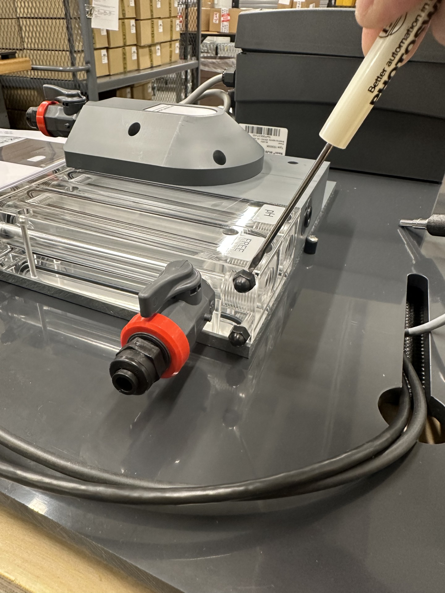
Step 1: Removing the Front Threaded Rod
- Identify the top front-facing threaded rod in the flow cell compression slot (Part #25).
-
Remove ONLY the front rod – this component applies pressure to the O-ring to maintain a watertight seal and secures the FTG sensor insert components (Parts #20-22.1).
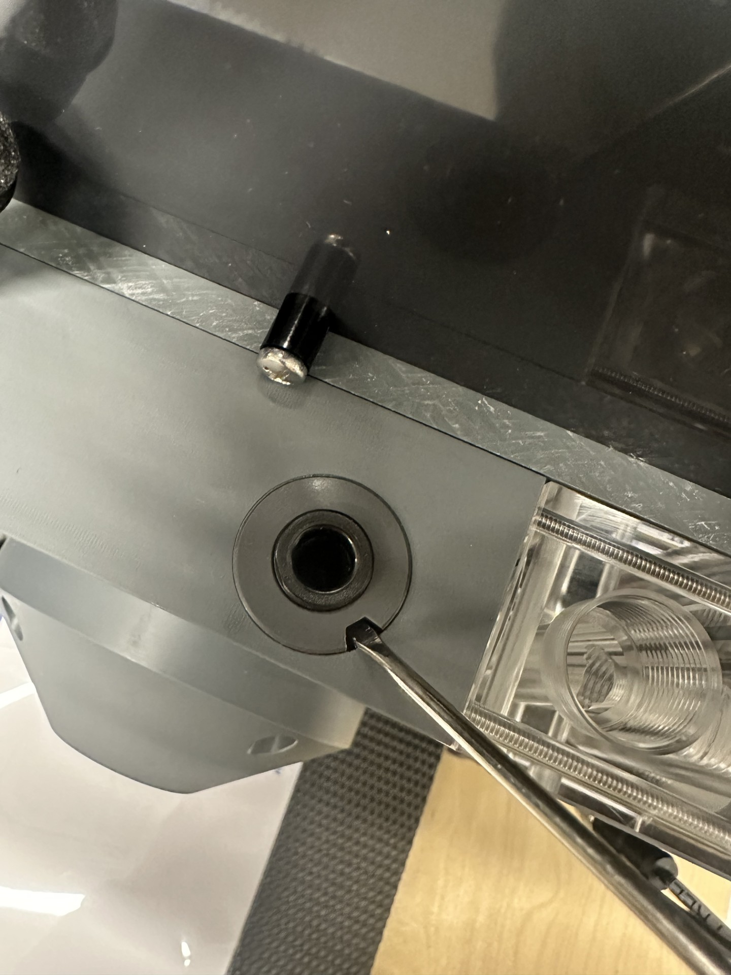
Step 2: Extracting the FTG Housing
- Use a small flat-headed screwdriver and insert the tip into the slot on the FTG housing (Part #20).
-
Apply upward pressure to gradually lift the FTG housing components out of the assembly.
Step 3: Accessing the Magnetic Float
- With the FTG housing components removed, you can now access the magnetic float (Part #23).
- To retrieve the float:
- Use a small magnet to pull it out, OR
- Flip the flow cell upside down and let the float fall out.
Step 4: Cleaning the Float and Flow Switch Components
- Carefully clean the float and surrounding flow switch components to remove any debris or buildup that may affect performance.
Step 5: Reassembly & Precautionary Measures
- Reinsert all components following the Exploded View of the Argon StabiFlow® Assembly.
- When reinstalling the compression rod (Part #25):
- Do not overtighten—excessive force could damage the flow cell and affect its integrity.