


Table of Contents
Do you need support?
Our team will be happy to assist you.
Installation of KRYPTON®ONE
Overview
The KRYPTON® ONE system is delivered pre-mounted on PVC panels with all core components pre-installed and wired. This guide covers the final on-site installation steps.
System variants:
- KRYPTON® ONE | COMPACT – Measurement and control in one enclosure
- KRYPTON® ONE | HUB – Includes additional relay outputs for extended control
What’s Pre-Installed
The KRYPTON® ONE system arrives fully pre-wired and ready to install:
- NEON® ONE CORE or COMPACT (central unit)
- NEON® ONE HUB (if HUB version) – HUB cable pre-connected
- STABIFLOW® ONE (flow assembly)
- ZIRKON® ONE FT sensor (flow & temperature)
- NEON® ONE NODEs – NODE cables pre-connected
- Power cable pre-connected
On-site installation only requires:
- Mounting the panel
- Inserting sensors and attaching NODEs
- Connecting water supply
- Connecting power cable to mains
Installation Steps
Step 1: Mount the Panel
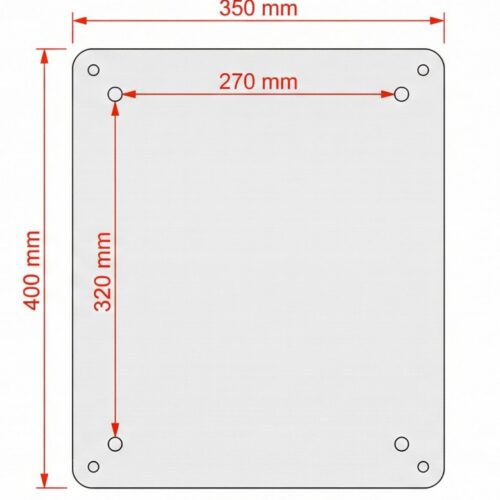
- Select a flat, vertical wall surface
- Use the included mounting brackets
- Mount with four screws and appropriate wall anchors
- Mounting hole spacing: 270 × 320 mm
The brackets maintain clearance between panel and wall for cable routing.
| Installation Requirements | |
|---|---|
| Location | Indoor, protected from moisture and direct sunlight |
| Ambient temperature | 0°C to +50°C (32°F to 122°F) |
| Humidity | Max. 90% rH at 40°C (non-condensing) |
| Protection rating | IP65 |
Step 2: Insert Sensors into STABIFLOW® ONE
- Identify the sensor positions on the STABIFLOW® ONE flow assembly
- Insert each ZIRKON® ONE sensor into its threaded port
- O-rings are pre-installed – hand-tighten only, no tools required
Important: The ZIRKON® ONE DIS sensor must be installed in the last chamber of STABIFLOW® ONE when using ASR® (Automatic Sensor Cleaning).
Step 3: Attach NODEs to Sensors
The NODE cables are already pre-connected to the NEON® ONE. Simply attach each NODE to its sensor:
- Take a NODE (cable is already connected)
- Attach the NODE onto the sensor head (click-fit)
- Repeat for all sensors
The NODEs click onto the sensor heads – no tools required.
Step 4: Connect Water Supply
- Connect inlet hose to STABIFLOW® ONE inlet
- Connect outlet hose to drain
- Ensure minimum inlet pressure: 0.5 bar (between inlet and outlet)
- Minimum flow rate: 35 l/h
Step 5: Connect Power Supply
The power cable is already pre-connected to the NEON® ONE. Simply connect it to your mains supply.
| Power Options | |
|---|---|
| AC Power | 00–240 VAC, 50–60 Hz |
| DC Power | 24 VDC |
| Power consumption | < 60W (total system including HUB) |
- Connect the pre-installed power cable to your mains supply
- Ensure proper grounding according to local electrical codes
- Power on the system
Warning: Only qualified personnel should perform electrical connections.
Step 6: Verify NODE LED Status
After powering on, check the LED on each NODE:
| LED Status | Meaning | Action |
|---|---|---|
| Solid Green | Installation successful | Ready to use |
| Blinking Green | Sensor connected, no communication | Check cable connection to NEON® ONE |
| Solid Red | No sensor connected | Check sensor is properly inserted |
| Blinking Red | Wrong sensor type | Verify correct ZIRKON® ONE sensor |
After Installation
- Allow system to start up (30–60 seconds warm-up)
- Verify water flow is stable
- Check all sensor readings on the display
- Calibrate sensors according to your application
- Set up Cloud Connect® for remote monitoring (optional)
Note: Sensor Groups are pre-configured by Kuntze – no manual setup required in most cases.
Quick Installation Checklist
| ☐ | Panel mounted on wall |
| ☐ | Sensors inserted into STABIFLOW® ONE |
| ☐ | NODEs attached to sensors |
| ☐ | Water inlet and outlet connected |
| ☐ | Water flow verified (min. 35 l/h) |
| ☐ | Power cable connected to mains |
| ☐ | All NODE LEDs show solid green |
| ☐ | Sensor readings visible on display |